เรื่องของ “ประสาทหูเสื่อม” หนึ่งในปัญหาของการได้ยินที่ควรรู้
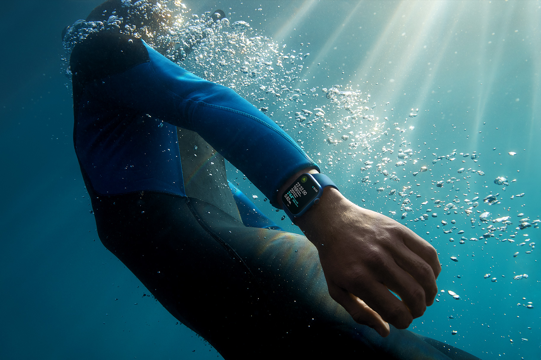
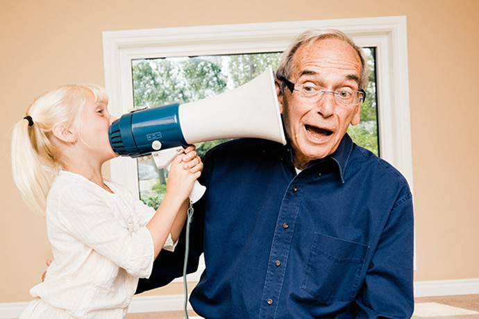
การได้ยินนั้นเป็นหนึ่งในปัจจัยที่สำคัญอย่างมากในชีวิตของเรา ซึ่งการได้ยินนั้นหากเปรียบเทียบกับการมองเห็นแล้วก็มีความสำคัญไม่แพ้กันเลยก็ว่าได้ เพราะว่าการได้ยินนั้นก็มีความสำคัญกับชีวิตของเราในหลากหลายเรื่องอย่างมากไม่ว่าจะเป็นการดำเนินในชีวิตประจำวัน และ ในเรื่องของการได้ยินนั้นหนึ่งในปัญหาที่พบและเจอกันอย่างแพร่หลายด้วยเช่นกันนั้นคือ “ปัญหาของ ประสาทหูเสื่อม” ซึ่งเป็นอีกหนึ่งในเรื่องของปัญหาที่สำคัญอย่างมากด้วยเช่นกัน ดังนั้นในบทความนี้เราจะมาดูกันในเรื่องของประสาทหูเสื่อม ที่เรานั้นควรที่จะรู้ไว้ และ ป้องกัน โรคเส้นประสาทหูเสื่อม โรคเส้นประสาทหูเสื่อมนั้นเป็นไปได้หลากหลายสาเหตุอย่างมาก ไม่ว่าจะเป็นสาเหตุจาก อายุที่มากขึ้น หรือ อีกหนึ่งในสาเหตุนั้นคือการใช้ชีวิตประจำวันของเรา และ พฤติกรรมในชีวิตประจำวันของเรา สิ่งแวดล้อม และ ปัจจัยเสี่ยงต่าง ๆ ซึ่งจะทีทั้งการหายไปของเสียงแบบบเฉียบพลัน หรือ เสียงที่เรานั้นได้ยินจะค่อย ๆ ได้ยินแบบเบาลง และ หายไปในที่สุด เสียงที่ได้ยินไม่ควรที่จะดังเกิน 80 เดซิเบล และ ไม่ควรนานจนเกินไป ปกติแล้วในการทำงานนั้นสำหรับคนในอุตสาหกรรมที่ทำงานพื้นที่ที่มีเสียงที่ดังมาจนเกินไปนั้นมีโอกาสที่จะ ป่วยเป็นผู้ป่วยที่มีปัญหาทางการได้ยินหรือ ประสาทหูเสื่อม ได้มากกว่าคนทั่วไปอย่างมาก เพราะว่าด้วยเครื่องจักรอุตสาหกรรมที่มีเสียงที่ดังมากจนเกินไป ดังนั้นจึงมีการออกฎหมายไม่ให้เครื่องจักรนั้นทำงานดังเกิน 80 เดซิเบล และ จะต้องไม่ทำงานหรือ ฟังเสียงที่ดังเกินไป ในเวลา 8 ชม. และ ที่สำคัญนั้นทางโรคงานอุตสาหกรรมนั้นควรที่จะมีที่ครอบหูให้กับพนักงานเพื่อป้องกันเส้นประสาทหูเสื่อม ปัจจัยที่มากขึ้น ก็ส่งผลต่อการได้ยิน […]